class home pages:
- GEOL5690 Western U.S. Tectonic History (Spring 24)
- GEOL4714/5714 Field Geophysics (Fall 24)
- GEOL1012 Intro Geology for Scientists (Fall 24)
- GEOL4717/5717 Field Seminar in Western U.S. Geology (Spring 23)
- GEOL5001 Physics and Chemistry of the Earth (Spring 23)
- GEOL5703 Tectonics Seminar (Fall 19)
- FYS001-049 Mtns Made Modern America (Fall 18)
- GEOL6650s.2 Earthquake seismology (Fall 17)
Web of Science ID
ORCID: 0000-0002-1698-0408
collaborative project pages:
- Sierra Drips CD (2006-10)
- Sierra EarthScope (2005-9)
- Sierran Paradox (1997)
- Southern Sierra CD (1993)
- New Zealand (2000-1)
Applied Geophysics Software update page
blog and COVID diaries
Mac PaleoMag (updated 5/15/20)
web
earthquake pages
mapping software (ANCIENT)
Craig H. Jones
Professor, Department of Geological Sciences, CU-Boulder
Fellow, CIRES, CU-Boulder
Chair, Geophysics PhD Program Committee
Ph.D., 1987, Massachusetts Institute of Technology
B.S., 1981, California Institute of Technology
Welcome to my website. My research focuses on the tectonics of the western United States, combining techniques from seismology, tectonophysics, paleomagnetism, field geology, gravity, magnetics, and structural geology. Resources related to this work can be found through the links at left.
Potential graduate students please read this!
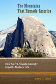
The Mountains that Remade America: Available now. Errata here.